

Production is shut down! Oil has leaked everywhere. Management is screaming to get the line going again. You hit the GO button and nothing moves. You’ve done some troubleshooting; you’ve got power, you’ve got a functional hydraulic system. Everything is working except for one function. All these signs tell you that a hydraulic valve is the culprit. You race to the stock room and grab a replacement. It bolts up to the same place, works on the same voltage, plugs back in without any new wiring, and it seems everything is resolved.
But, when you power up the machine, one of the motions moves in when it is supposed to move out. A conveyor turns off when it is supposed to turn on. Downtime is extended. The machine is possibly damaged. Or worst case, at rest, a heavy device begins to change position when it is supposed to be held in place. What went wrong?
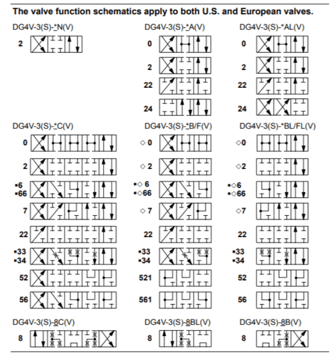
A directional valve with the same size body – same size ports – same electrical connections – can do a variety of different functions and all you need to do is change the spool! Externally, the valve will look exactly the same but internally the flow paths may be completely different. They all look the same but they are not! Great care must be taken when grabbing a valve off the shelf!
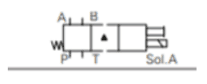
Referring to the chart above, let’s start with a basic valve body. This valve below has a solenoid on one end and a spring on the opposite end.
Now we are going to insert the spool into the body. This is an Eaton-Vickers #2 Spool.
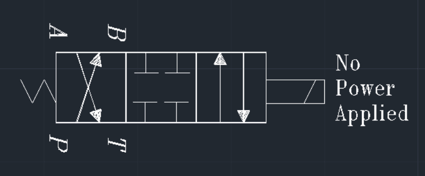
By combining the two Pictures, we get a full valve operation.
Shown here, the valve is in its non-energized position. The Spring is in control. Pressure comes in the P port (if that is how the system is piped) and out to B port. The A work port is flowing to the Tank or Return.
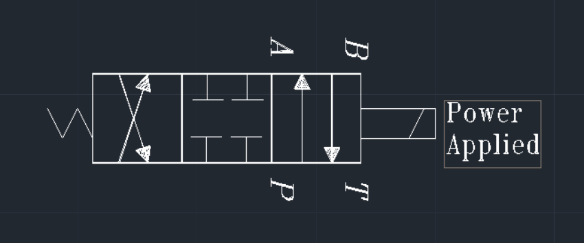
When the Solenoid is energized, the valve shifts to opposite position (see below). The Pressure now goes straight up to the A work Port. The B work port now goes to Tank. The middle position can either be a third position or not utilized. If not utilized, the middle position becomes a transition. When utilized, the middle position can hold a device in position or release the pressure on a device.
For that example, I chose one spool from the chart and filled in the blanks. Now look again and see some of the options on the initial chart. Just on this chart, there are 13 spool options. Now we can start choosing operator options for each end of the spool. Hydraulic, manual, solenoid, spring, proportional, are just a few. The chart below shows several 3-position spools and their transitional states. It tells what happens while the spool is shifting.
In the transitional state, sometimes the pressure is held and sometimes it is relieved. This must be accounted for in load holding and precise motions. Depending on the spool, you can choose what happens during the transition. In a lot of cases, the transition is so fast, you won’t notice either way. In some applications, the transition can be critical.
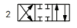
#2 Spool – Standard Directional Valve for Cylinder Operation – Blocked Center.
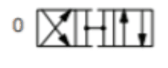
#0 Spool – Same as Above – All Ports Relieved in Center Position.
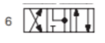
#6 Spool – Motor Spool – Both Work Ports to Tank in Center Position.
This is also used on cylinder control when cylinders have load holding checks or counterbalance valves.
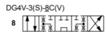
#8 Spool – Tandem Spool.
This spool is used on some circuits to unload a pump in the center position. When sized properly, this can be a very handy valve.
When it comes to selecting the correct valve for an application, you can’t go by sight. You must match part numbers and operational specifications. In today’s markets, as products become harder to find and lead times are becoming more challenging, contact a Certified Hydraulic or Certified Fluid Power Specialist from Cross Company to help with an inventory plan for your OEM application!


Sign up for our newsletter to get industry trends, educational content, and product updates, the way you want to receive them.
© 2023 Cross Company. All rights reserved | Privacy Policy | Terms and Conditions
Design Collaboration and Hosting by Drum Creative
"*" indicates required fields
We’re looking through thousands of pages to find the most relevant information.
In the meantime, enjoy these fun facts…