Understanding Machinery Electrification
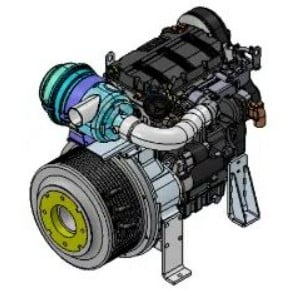
As the trend toward electrification of mobile equipment accelerates, it is becoming increasingly apparent that simply looking at the power rating of the current Internal Combustion Engine (ICE) and using that to assume battery power requirements is not enough. In most cases, this leads to an overestimation of the piece of equipment’s battery needs which can be a very costly mistake, and in many cases make the project financially unfeasible.
Understanding The System Design - Hydraulic Efficiency
The first step to launching a successful electrification project is to understand the power requirements of each individual function on the machine. Why is this important? In many cases, hydraulic systems have not been designed to be as efficient as possible, but rather to get the job done at the lowest possible cost. This is not poor design, but rather a reflection of the need to balance design elegance with costs, which are critical in most markets. Because of the costs of electrification components, it becomes much more important to right-size each individual actuator in order to ensure maximum efficiency, and to correctly size your battery pack.
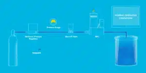
Consider a simple example where a machine uses a single cylinder to perform some function. In this example, 5 GPM@3000PSI is required to deploy the cylinder and we are using a simple fixed pump system design that actually generates 10 GPM.
Hydraulic Horsepower is calculated as:
HP = P*Q/1714
where:
P – Pressure in PSI
Q – Flow in GPM
In this example the system would be dumping 5 GPM over the system relief at 3000 PSI which equates to 8.75 HP in wasted energy during the cylinder cycle. While this example is certainly oversimplified for most machines, it illustrates a very important concept: many current system designs can result in significant wasted energy, which can be a very costly mistake in a battery powered system.
Understanding Duty Cycle
The next step in a successful electrification project is to truly understand how a machine is operated. While this may seem overwhelming, it is important to instrument the pressure and flow at each work function and run the machine under real-work operating conditions. A few hours of data recording will yield useful information regarding peak loading and duration. You can easily oversize electric motors if you size for peak loading only, and not take into effect work cycle duration. To properly size an electric motor, let’s take a look at the following example:
Motor A – with data recording, you determine that a work function requires 17.17 gpm at 2000 psi. The current hydraulic motor is running at 2500 rpm. Based on these data points, you can calculate motor kW, and torque required.
HP = Pressure * Flow/1714
HP = 2000 * 17.17/1714 = 20.04
kW = HP/1.341
kW = 20.04/1.341 = 14.94
Torque = 9.5488 * Power (kW)/Speed
Torque = 9.5488 * 14.94/2500 = 0.05706 x 1000 = 57.06 Nm
Now that you have calculated motor torque and power required, the next step is to understand how often and for how long this machine function is used. For example, does motor A run the boom on the machine for 2 minutes every 25 minutes? Does one type of user run the boom for 5 minutes every 15 minutes, and someone else runs it differently? All of these factors, peak loading and duration, and how a machine is used, determines how to size your battery pack for battery system optimization.
Continue reading to learn about Battery System Optimization, then contact an expert at Cross to discuss your electrification needs.