Are You Replacing Valves Too Often?
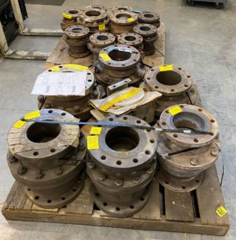
Are Your Valves Lasting a Year or Less in Your Application?
If the answer to this question is “yes”, then you may have the wrong valve for your application. There are several critical factors to consider when selecting a valve. Selecting the right valve for your application conditions can help you to reduce your risk of downtime which will save you both time and money in the long run. These are some of the top factors to consider. If you can provide your valve supplier with this information they will be better equipped to find the right valve for your application.
Knowing the temperatures that your valve will experience is important for seat selection and body material selection. For our purposes, anything above 450° F is considered high temperature and would require a metal seat. For low temperature applications (below 450° F) you can use a soft seat material such as a teflon (PTFE) or a reinforced teflon (RTFE). We do however have some manufacturers who can solve some high temperature applications (425°-525°F) with a soft seated teflon copolymer derivative material. This is helpful, as soft seated valves tend to be less expensive than their metal counterparts. If your process runs at very cold temperatures (down to -320° F) you will also need special valves. Cross has valves capable of handling these extreme temperatures for cryogenic service.
An important thing to remember is that there can be significant temperature swings within your process that can impact the performance of your valve. For instance, if your normal process temperature is 200° F it could fluctuate from 150°-300° F within a short period of time. This is why you need a valve with good seating technology. This is also true for applications where the process lines need to be cleaned between runs. If you are using steam to clean the lines, the high temperature steam could melt your valve components.
Another temperature related consideration is whether or not your material could solidify if the temperature drops. If this happens the material can build up around the ball and seat causing damage. Examples of materials that could do this include monomers, butadiene, and styrene. In these cases, you may need a steam jacket or heat tracing on the piping around the valve to ensure the media continues flowing at a steady rate.
Continue reading about the additional factors concerning valve replacement, then reach out to a Cross Process Solutions representative to discuss your application.
Our Calibration Flow Lab is Now Located in Knoxville
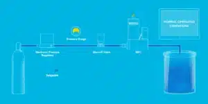
We have exciting news to share with you – our flow meter calibration lab has relocated to Knoxville, TN and is ready to service your flow meter equipment!
Cross is your one stop shop for a range of flow meter calibration services. We offer ISO 17025 accredited calibration of mass flow controllers and mass flow meters using our Fluke Molbloc System.
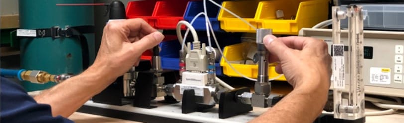
Our team of flow experts can help you through all stages of your equipment’s life cycle from purchasing new equipment to routine maintenance, as well as repair and eventual replacement. Gas Flow Calibration Services include:
- Variable Area Flowmeters
- Mass Flow Controllers
- Mass Flow Meters
- Diaphragm Flow Meters
- Flow Verification
- Specifying New Flow Meters
Contact a Cross Process Solutions expert to coordinate your flow meter calibration requirements.
How to Tune a PID Loop
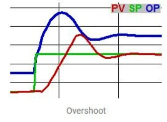
The art of tuning a PID loop is to have it adjust its output (OP) to move the process variable (PV) as quickly as possible to the set point (responsive), minimize overshoot, and then hold the variable steady at the set point without excessive OP changes (stable).
Definitions
- PID = Proportional, Integral, Derivative algorithm. This is not a P&ID, which is a Piping (or Process) and Instrumentation Diagram.
- PV = Process Variable – a quantity used as a feedback, typically measured by an instrument. Also sometimes called “MV” – Measured Value.
- SP = SetPoint – the desired value for the PV.
- OP = OutPut – a signal to a device that can change the PV – frequently a valve, damper, or a pump speed reference. Often called “CV” – Controlled Value.
- Overshoot = when the PV moves further past the SP than desired.
- A PID loop in manual (as opposed to automatic) only changes its OP upon operator request.
- A loop in remote (aka cascade) has its SP automatically adjusted by external logic. In local the SP is only changed by the operator.
- A direct acting PID loop increases its OP in response to increasing PV, while a reverse acting loop decreases its OP. “Normal” loops are reverse acting. Loops controlling level or pressure via a valve on an output, or temperature via cooling are generally direct acting – “backwards” loops.
- Error = the difference between PV and SP.
Continue reading about the three basic tuning parameters of a PID loop, as well as additional factors such as linearity and hysteresis, then reach out to one of our engineers to discuss your particular PID concerns.