
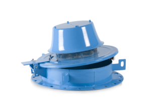
Meinecke Turbine Flow Meters are available in sizes ranging from 1-1/2″ to 12″. Cold Water Meters are rated to a maximum temperature of 122’F, Hot Water Meters are rated to 256’F. Even though this is a mechanical meter at its core, output options are available. When used with a remote totalizer, Reed Pulsers are available, but for the purposes of this post, we’re going to concentrate on the “other” output.
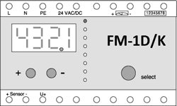
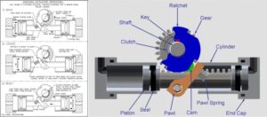
For a remote indication of flow rate, consider using an Opto Pulser and and FM-1D/K Transmitter, otherwise known as a “Frequency to Current Converter”. In it’s simplest terms, Opto Pulsers shine an infrared light on a star shaped, reflective wheel within the register. With flow, the wheel spins and the pulser counts the reflections coming back at it from the wheel. That count, also referred to as a “Frequency” is reported to the FM-1D/K and then “converted” to 0-20 or 4-20mA output. For your convenience, there is also a display of flow rate located on the transmitter.
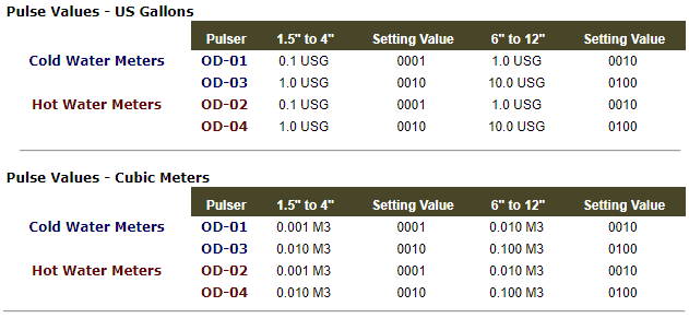
Different size meters, as well as those designed for measuring Cold or Hot Water have different Pulse Values. In this tutuorial, I’ve used a 3 inch cold water meter as an example, but pulse values for all meters sizes and types are included at the end of this article.
Once the unit has been connected and powered up, refer to Section 4 of the operations manual”Calibration by Hand”. We’ll work through sections 4 – 7 here. In this instance, we are programming the FM-1D/K for use with a 3 inch cold water meter and a Model OD-03 Opto Pulser.
Water Meter: 828601 3″ Cold Water Meter
Pulser: Type: OD-03
Current Output: 0-20mA or 4-20mA
Flow Rate: 3.5 to 528 GPM
Pulse Output: 1 pulse = 1 US Gallon
Flow Range
The Maximum Continuous Flow for this meter is 528 GPM. When turning the unit on for the first time, the display should show “0000”. Press + or – to enter the programming mode and then adjust the digits (starting at the left) using the + or – buttons to match the maximum flow. If you want the output to reflect the full range of a 3″ meter, we suggest you change it to 0550. This gives you a possible flow range of 0 to 550 GPM which is just slightly more than the rated 528 gpm.
Counter Reading
The purpose here is to sync the actual meter reading with the FM1-D/K display. If this isn’t important to you, skip this step. Using the Upper and Lower Status lights as directed, set each digit to match the reading on your flow meter. Don’t forget that the full eight digit readout includes the last two or three digits indicated by the red tip of the dial.
Pulser Input
The pulse value for the OD-03 on a 3 inch meter is 1 pulse = 1 gallon so you will need to set this to 0010. Also, on the input value, the signal mode should be set to InPb. It shouldn’t make a difference if it’s not, but the correct setting is InPb. This setting tells the unit that the OD-** pulser is only capable of detecting flow in one direction only.
Pulse Output
This reading is used for two purposes, the integral display and the pulse output to a remote totalizer (if used). When configuring this setting, it needs to be equal to or greater than the input value. In this application with an input value of 0010, the setting needs to be 0010 or greater.
Output Setting
This setting allows you to choose between 0-20mA or 4-20mA. Toggle between them with the +/- buttons and use the “Select” button to make your choice.
Damping
This setting determines the response time of the current output and flowrate indicator. Damping ranges from 1 (No Damping) to 14 (Maximum Damping). If there are no special requirements, the factory recommends a damping of “0004” for most applications.
Settings to the FM-1D/K can be protected against unintentional changes by using this feature. Once the programing has been completed, tested and the unit is ready for use, press both the + and – buttons simutaneously to toggle back and forth between the Programming and Protected Modes. In the Protected Mode, the settings are still visable, but cannot be changed.
Display: “LOC 6” = Device in Programming mode
Display: “LOC 8” = Device Protected
Follow the manufacturers recommendations/instructions as needed.
Follow the manufacturers instructions to test your settings. The +/- buttons are used to scroll through the test modes.
Are you interested in learning more? Fill out our contact form with some details of your application and we’ll have a specialist get in touch! Also, learn more about Meinecke as a products and solutions provider for Cross.


Sign up for our newsletter to get industry trends, educational content, and product updates, the way you want to receive them.
© 2023 Cross Company. All rights reserved | Privacy Policy | Terms and Conditions
Design Collaboration and Hosting by Drum Creative
"*" indicates required fields
We’re looking through thousands of pages to find the most relevant information.
In the meantime, enjoy these fun facts…