FS10i Flow Switch and Monitor
Product Overview
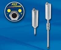
The FS10i is a universal flow switch and flow monitor designed for simple insertion into ½” (13mm) or larger diameter pipes and square ducts. Suitable for either liquid or air/gas applications it is fast responding and highly repeatable to both increasing and decreasing flow rate changes.
Providing best-in-class features, the FS10i is ideal for rugged duty applications and is built for long-life usage in a range of other industrial process applications. For more information about the FS10i flow switch and monitor, contact a Cross process solutions expert.
As an exclusive representative for Fluid Components International, Cross offers the complete line of FCI flow equipment throughout our territories in the mid-Atlantic area, including; Maryland, Virginia, and Washington D.C.
Features
- Cooling water and fluids
- Lubricant flow assurance
- Ventilation flow assurance
- Relief valve monitoring
- Nitrogen purge verification
- Leak detection
- Chemical injection
- Filter blockage/change indication
- Compressor operation assurance
- Compressed air/gas leak alarm
Specifications
Materials of Construction (Wetted Parts): 316L SS with Hastelloy C-22 thermowells
Flow Sensitivity/Setpoint Range:
- Water: 0.01 FPS to 0.5 FPS [0,003 MPS to 0,15 MPS]
- Air/Gas: 0.25 FPS to 400 SFPS [0,076 MPS to 122 MPS]
Repeatability: ±0.5% of reading
Temperature Coefficient For temperatures > ±30°F [±16°C]
- Gas: Maximum ±0.025% of reading/°F up to 250°F [±0,05% of reading/°C up to 121°C]
- Liquid: Maximum ±0.2% of reading/°F up to 250°F [±0,367% of reading/°C up to 121°C]
Operating Temperature:
- -40°F to 250°F [-40°C to 121]
- Teflon ferrule maximum temperature is 200°F [93°C]
Operating Pressure:
- 2000 psi [138 bar]
Teflon ferrule maximum pressure is 150 psig [10 bar(g)]
Insertion “U” lengths:
- 2″[50 mm] fixed
- 6″[150 mm] with variable insertion depth, compression fitting with Teflon or metal ferrule
Electronics
Display: 10 segment LED array, sequential lighting related to flow rate and flashing when trip point exceeded
Output Signals:
- Relay: SPDT, 1A @ 24 Vdc, 120 Vac Analog: 4-20 mA trending*
- Serial: RS232C I/O
*500 ohm maximum load; user scalable, general purpose, uncalibrated output proportional to flow rate for trend monitoring or assignable to temperature; fault indication per NAMUR NE43 guidelines, user-selectable for high (>21.0mA) or low (<3.6mA) default
For linearized and calibrated analog outputs, see FCI’s line of thermal mass flow meter products
Operation: Two top-mounted buttons to program switch/trip point, zero and span setting, fail-safe, relay hysterisis and relay time delay; button operation may be user disabled to prevent unwanted changes; all set-up function are also user programmable via the RS232C serial port
Trip Point Hysteresis Control: 0-100% of span
Trip Point Time Delay: user settable for 0-65,000 seconds
Input Power: 24 Vdc (21.5 Vdc to 30Vdc); 2.5 watts maximum
Operating Temperature: -40°C to 160°F [-40°C to 71°C]
For full specifications, including certifications, agency approvals and ratings, download the product specification sheet below.