When someone says a system is “load sensing,” it means that it has been designed to operate at as low a flow and/or pressure as possible when no functions are actuated, and is able to immediately “jump” back up to the flows and pressures necessary to do the work demanded. The advantages of this are lower total energy use (in the form of engine fuel or electricity in the prime mover), less heat created, and longer component life. As with most things in mobile hydraulics and controls, there is more than one way to accomplish this feature.
Load Sensing With a Pump Compensator
The most commonly applied technology today seems to be the hydraulic load sensing compensator as part of a variable piston pump. This compensator works in conjunction with a pressure cut-off compensator that controls the maximum pressure the pump will seek. A small hydraulic line connects the “LS” port on the load sensing compensator to the “LS” port on the valve that diverts flow to one or more functions. If there is no valve in the circuit specifically designed to communicate a load sense signal, then connecting the line beyond the valve and near the actuator is acceptable.
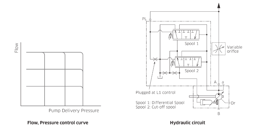
When the actuator is not functioning, there is no pressure communicated by the load sense line, and the pump reverts to a standby mode. This means that it de-strokes to a smaller amount of flow that corresponds to a low “standby” pressure (set at the load sensing compensator) of generally 250-350 psi. When additional pressure is encountered, it is communicated to the pump via the load sense line. The pump seeks equilibrium by creating more flow until either the required actuator pressure + standby pressure is met, or the maximum pressure cut-off setting is met
An advantage of this system is a high level of overall efficiency. A disadvantage may be cost, depending on component choice. Another disadvantage may be “sluggish” actuator engagement as the pump receives its signal to provide more flow. This will be affected by the length and expansion of the load sense line and the response time and accuracy of the pump control design. If there is a critical function that needs to have extremely “crisp” and consistent feel, then this may not be the best choice. Don’t immediately assume this is the best way just because it is the most common.
Load Sensing with a Flow Sharing Valve and Fixed Displacement Pump
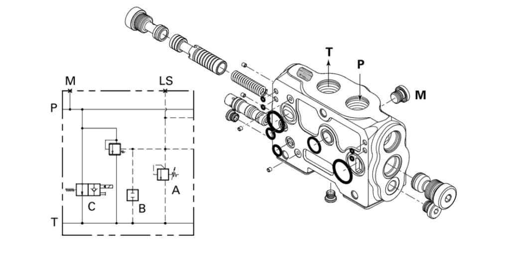
Another method of load sensing relies mainly on the valve and allows for a basic, fixed displacement pump to be used. This is typically an available feature of a flow sharing, multi-section valve bank. An inlet will accept all of the pump flow and give it a low-pressure path to tank when no functions are actuated. There are internal “load sensing” pathways in the valve that communicate the highest demanded actuator pressure to the valve inlet. The inlet of the valve will restrict the flow from the pump until enough pressure is created to match what is required to move the load.
An advantage of this type of system can be the cost, but the disadvantage will be the efficiency of the pump and potentially fluid cleanliness as described in our article about pairing piston and gear components.
Typically, the flow sharing valves capable of what is described above will require high fluid cleanliness. A pressure filter between the pump and valvebank would not be a bad idea to keep any contamination from the pump from getting to the valve. This method should result in more “crisp” function feel because there is no delay for the pump to build up the flow. There is still theoretically a delay, though, while the valve inlet restricts the flow enough to build required pressure when your function requires it.
Electronic Pump Displacement Control
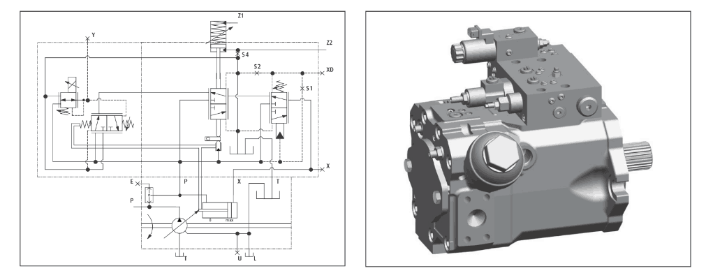
A third method – electronic pump displacement control – is the most cutting-edge technology and seeks to overcome the disadvantages of the hydraulic load sensing pump compensator. This has been around for years in the closed circuit pump market but is becoming a strong option for open circuits because of the use of electronic controllers that can manage pump flow in relation to the signals it is sending to a valvebank.
If a controller sends a signal to a valvebank section that will require 4 gpm, it simultaneously will send a signal to the pump displacement control that results in an additional 4 gpm of pump flow. Bingo. Done. No worries about balancing load pressure across spools, expansion in hoses, or competing functions impacting the hydraulic signal.
In reality, this is not “load sensing” at all, because this method does not require any signal from the load. It proactively generates exactly what it already knows the load will require. The challenge here is that a central controller must exist and be programmed correctly. It can allocate flow and even assign priority electronically to the valve functions in case the pump runs out of available flow.
This is the absolute best method for a crisp response, energy savings, and advanced features such as function priority. The downsides are cost and initial programming time. This is also only suited for a completely electronic system with advanced input devices like HMI’s (displays), electronic joysticks, etc.
Select the Right Method for You
Choosing which method is best for your mobile hydraulic system may not be as straightforward as picking the most advanced and highest performing options available. There may be dimensional or mounting constraints that limit you to a small, fixed displacement pump. This would result in the load sensing valve solution being the most viable.
You may already be using a load sensing pump on other projects that can be selected to avoid expanding inventory. That would steer you towards the load sensing pump compensator solution with a simpler valve.
The electronic proportional control may be overkill for your system, but if you have tried other methods with mixed results, then it may be the solution for you. The best solution may even be not to worry about load sensing at all if you have very few functions or if efficiency does not outweigh cost as a design constraint.
Any load sensing system will be a vast improvement in energy savings and temperature over a pressure compensated system or most fixed displacement systems. If you are considering an upgrade or redesign of your current hydraulic system, then the experts at Cross Company can help!
How Cross Can Help
If you’re looking for experts in mobile systems (electric systems, hydraulic systems, mobile control components, or anything else), Cross can help. Contact the Mobile Systems Integration specialists at Cross Company today to discuss your application, vehicle, or prototype. We’re members of the National Fluid Power Association (NFPA), the Association of Equipment Manufacturers (AEM), the International Fluid Power Society (IFPS), and closely follow ISO standards for mobile machinery. With our experience and expertise, we can get you where you need to go.